Data Acquisition
Buffer
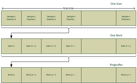
Fig. 18 Acquisition ringbuffer
Scan and Scan Size
One scan is the portion of data that consists of exactly one sample for each sampled channel on a board.
So if there are 2 analog channels and 1 counter channel active, the scan would logically hold three values. (AI0, AI1, CNT0).
The scan-size therefore directly derives from this information. It describes the memory-consumption of one scan in Bytes. In above example, when using the AI-channels in 24Bit mode (consuming 32Bit per Sample) the resulting scan size would be:
ScanSize := sizeof(AI0) + sizeof(AI1) + sizeof(CNT0)
Scansize := 32Bit + 32Bit + 32Bit
Scansize := 4 Byte + 4 Byte + 4 Byte
Scansize := 12 Byte
So one scan would have the size of 12 Byte.
The scan size cannot be directly controlled by the application as it directly depends on the number and type of activated channels.
Usually the application does not have to know very detailed about one scan and its layout inherently, as there are ways to get this information from the API in an abstracted way at runtime.
Block and Block Size
One block is a collection of n scans.
It is only meant as a logical unit and does not directly influence the driver in any way. Usually it is set up in accordance with the polling-interval of the application.
The block-size can be set to any arbitrary value > 0. A standard use case would set it to SampleRate * pollingIntervall. For Example:
BlockSize := SampleRate * pollingIntervall
BlockSize := 2000 SPS * 0.1 sec
BlockSize := 200
This has to be set by the application.
Block Count
This defines how many blocks the buffer shall be able to hold. This allows the application to control how big the backlog of data shall be and thus how much time the application may spend with tasks not related to the acquisition – so that peaks in computation times won’t lead to lost acquisition data.
It can be set to any value > 0, and is only limited by the total available memory.
For example:
BlockCount := 50
This has to be setup by the application.
Total Buffer Size
The total buffer size is calculated based on the above described information.
Buffersize := ScanSize * BlockSize * BlockCount
In our example:
BufferSize := 12 Bytes * 200 * 50
BufferSize := 12 Bytes * 10000
Buffersize := 12000 Bytes
Synchronous Data Channels
Each sampling period produces one sample for each channel and consumes “Scan Size” amount of data in the buffer. There are currently three kinds of synchronous data in the buffer: analog channel samples, counter channel samples and digital channel samples.
The driver itself maintains a separate read- and write-pointer into this buffer. So the hardware can add new samples independent of the applications data-processing.
The driver will notify the application with an error-code if a buffer-overrun occurs. That is, if the application processes data too slow, so that the new samples have already overwritten unprocessed old ones.
The application then can freely decide how to handle this error case.
Buffer Setup and Buffer Ownership
The buffer itself is completely maintained inside the API – so the applications do not have to bother with allocation and de-allocation issues, which usually come with having a buffer.
However – to allow the application a fine granulated control over the buffer, it is able and obligated to indicate to the API the desired size of the buffer in terms of logical units, by using the integer-based functions. The application decides, how many scans one block shall hold, and how many blocks shall be allocated. The actual size in bytes is then calculated by the API and the buffer is allocated.
Buffer Readout from Application Point of View
The ring-buffer is exposed to the application by providing the related pointer information.
The API will provide:
Start-pointer of the ring buffer
End-Pointer of the ring buffer
Pointer to the first unprocessed scan
Together with the information how many unprocessed samples are available the application iterates directly over the ring buffer.
This approach allows a minimal internal overhead on data-access.
Scan Descriptor
As mentioned before a scan is the portion of data containing exactly one sample per used channel. Without knowledge about its internal layout, this would just be a binary stream with arbitrary length.
But the application does not need to know implicitly about the layout of the data. This would be undesirable, as the layout may change with coming driver versions or coming hardware. For example, when a new type of synchronous data will be added, inherent hardcoded knowledge within the application would immediately break the data-readout mechanism of the application.
So after setting up the acquisition environment, the API can be queried about the layout.
The detailed layout-information will be returned as an XML-string.
<ScanDescriptor>
    <BoardId0>
        <ScanDescription version="2" scan_size="96" byte_order="little_endian" unit="bit">
            <Channel type="Analog" index="3" name="AI3">
                <Sample offset="32" size="24" />
            </Channel>
        </ScanDescriptor>
    </BoardId0>
</ScanDescriptor>
Scan Descriptor Structure
The following API string command returns the scan information for a specific Board:
DeWeGetParamStruct_str( "BoardId0", "ScanDescriptor_V2", Buf, sizeof(Buf));
The returned XML document correlates with the following hierarchy:
<ScanDescriptor> : XML Element. Max. Occurrences: 1.
<BoardID0> : XML Element. Max. Occurrences: 1.
<ScanDescription> : XML Element. Max. Occurrences: 1.
<Channel> : XML Element. Max. Occurrences: Unbounded.
<Sample> : XML Element. Max. Occurrences: Unbounded.
Please be aware that the scan descriptor annotates only the enabled channels for a specific Board. In case no channel is enabled, the API returns an empty scan descriptor with “scan_size” set to the value 0.
The API considers disabled channels and therefore the returned “scan_size” and “offsets” are being returned accordingly.
The following list depicts all possible XML Elements and their XML attributes and values of the returned scan descriptor XML document:
Element |
Attribute |
Description |
|---|---|---|
ScanDescriptor |
ScanDescriptor root element |
|
BoardIdXX |
Selected board elememt “BoardID0” |
|
ScanDescription |
Describes the scan for the requested board |
|
version |
Scan descriptor’s document version (Should be 2) |
|
scan_size |
The size of the scan expressed in unit |
|
byte_order |
The byte order of the scan (“little_endian”) |
|
unit |
The unit of “scan_size” attribute (“bit”) |
|
Channel |
Channel element |
|
type |
Value: string “Analog”, “Counter”, “Discrete” |
|
index |
The channel index on the specific board |
|
name |
API name of the channel “AI0” |
|
Sample |
Detailed sample description |
|
offset |
The offset within the whole scan |
|
size |
the size of the sample |
|
subChannel |
Optional attribute for counter sub channels |
Warning
When requesting a scan descriptor with command “ScanDescriptor” (Version 1), some boards may not be able to return a valid scan descriptor for analog 24bit channels. Therefore, always use “ScanDescriptor_V2”.
Warning
“ScanDescriptor” version 1 is deprecated and will be removed. It will return the V2 document in future.
Scan Descriptor Example Source Code
The next example extends the Quickstart app with a valid Scan Descriptor support class.
  1#include "dewepxi_load.h"
  2#include "dewepxi_apicore.h"
  3#include "dewepxi_apiutil.h"
  4#include "pugixml.hpp"
  5#include <functional>
  6#include <iomanip>
  7#include <iostream>
  8#include <string>
  9#include <vector>
 10
 11
 12/**
 13 * Functor to be implemented by applications interested in sample data.
 14 */
 15using AddSampleFunctor = std::function<void(const char*, uint32_t,
 16    const void*, uint32_t, uint32_t, uint32_t, uint32_t)>;
 17
 18
 19/**
 20 * ScanDescripterDecode
 21 * Uses ScanDescriptor_V2 xml allowing generic
 22 * sample decoding and processing.
 23 */
 24class ScanDescriptorDecoder
 25{
 26public:
 27    ScanDescriptorDecoder(const std::string& sd_xml, AddSampleFunctor f)
 28        : m_datasink(f)
 29    {
 30        parseScanDescriptor(sd_xml);
 31    }
 32
 33    /**
 34     * parseScanDescriptor - parses V2 xml and build internal processing vector
 35     */
 36    void parseScanDescriptor(const std::string& sd_xml)
 37    {
 38        pugi::xml_document sd_doc;
 39        if (pugi::status_ok == sd_doc.load_string(sd_xml.c_str()).status)
 40        {
 41            auto scan_description_node =
 42                sd_doc.select_node("ScanDescriptor/*/ScanDescription").node();
 43            if (scan_description_node)
 44            {
 45                if (2 != scan_description_node.attribute("version").as_int())
 46                {
 47                    throw std::runtime_error("Unsupported version");
 48                }
 49
 50                m_scan_size_bytes
 51                    = scan_description_node.attribute("scan_size").as_int() / 8;
 52                // Can be safely ignored:
 53                // bit
 54                // byte_order
 55                // buffer_direction
 56                // buffer
 57
 58                auto channel_nodes = scan_description_node.select_nodes("Channel");
 59                for (auto channelx : channel_nodes)
 60                {
 61                    auto channel = channelx.node();
 62
 63                    auto sample = channel.child("Sample");
 64
 65                    m_scan_desc_vec.push_back(
 66                        SDData{ std::string(channel.attribute("name").as_string())
 67                                , std::string(channel.attribute("type").as_string())
 68                                , channel.attribute("index").as_uint()
 69                                , sample.attribute("size").as_uint()
 70                                , sample.attribute("offset").as_uint()
 71                        });
 72                }
 73            }
 74            else
 75            {
 76                throw std::runtime_error("ScanDescriptor unexpected element");
 77            }
 78        }
 79        else
 80        {
 81            throw std::runtime_error("ScanDescriptor parse error");
 82        }
 83    }
 84
 85    /**
 86     * Process sample blocks
 87     * @param avail_samples a continuous block of samples
 88     * @return incremented read_pos
 89     */
 90    sint64 processSamples(sint64 read_pos, int avail_samples)
 91    {
 92        auto read_pos_ptr = reinterpret_cast<const char*>(read_pos);
 93
 94        for (const auto& sd : m_scan_desc_vec)
 95        {
 96            uint32_t offset_bytes = sd.sample_offset / 8;
 97            auto read_pos_ptr_chn = read_pos_ptr + offset_bytes;
 98            uint32_t channel_bit_mask = (1 << sd.sample_size) - 1;
 99            uint32_t channel_bit_msb = sd.sample_size;
100
101            m_datasink(sd.name.c_str(), sd.index, read_pos_ptr_chn, avail_samples,
102                channel_bit_mask, channel_bit_msb, m_scan_size_bytes);
103        }
104
105        return read_pos + (avail_samples * m_scan_size_bytes);
106    }
107
108private:
109    AddSampleFunctor m_datasink;
110    uint32_t m_scan_size_bytes;
111
112    struct SDData
113    {
114        std::string name;
115        std::string channel_type;
116        uint32_t index;
117        uint32_t sample_size;
118        uint32_t sample_offset;
119    };
120    std::vector<SDData> m_scan_desc_vec;
121};
122
123
124/**
125 * Data Sink - App interface
126 * @param channel is the name of the channel
127 * @param first_sample pointer to the first sample
128 * @param nr_samples number of samples available
129 * @param bitmask bit mask to apply to get the valid sample value
130 * @param stride is the offset to the next sample
131 */
132void addSample(const char* channel_name,
133            uint32_t channel_index,
134            const void* first_sample,
135            uint32_t nr_samples,
136            uint32_t channel_bitmask,
137            uint32_t channel_bit_msb,
138            uint32_t stride)
139{
140    const char* data_ptr = static_cast<const char*>(first_sample);
141
142    for (uint32_t i = 0; i < nr_samples; ++i)
143    {
144        uint32_t value = (*reinterpret_cast<const uint32_t*>(data_ptr)) & channel_bitmask;
145        std::cout << channel_name << ": " << std::hex << value  << std::endl;
146        data_ptr += stride;
147    }
148}
149
150/**
151 * Print samples in channel per column
152 * Uses Functor interface like "addSample"
153 */
154class FormattedOutput
155{
156public:
157    FormattedOutput(int num_channels, int block_size)
158        : m_num_channels(num_channels)
159        , m_block_size(block_size)
160    {
161        m_output_buffer.resize(m_num_channels);
162    }
163
164    void operator()(const char* channel_name,
165        uint32_t channel_index,
166        const void* first_sample,
167        uint32_t nr_samples,
168        uint32_t channel_bitmask,
169        uint32_t channel_bit_msb,
170        uint32_t stride)
171    {
172        const char* data_ptr = static_cast<const char*>(first_sample);
173
174        m_output_buffer[channel_index].chn_name = channel_name;
175
176        // copy samples in separate buffer per channel
177        for (uint32_t i = 0; i < nr_samples; ++i)
178        {
179            // The bitmask has to be applied to cut out the correct value.
180            // The MSB has to be checked to sign extend negative values
181            int32_t value = (*reinterpret_cast<const int32_t*>(data_ptr)) & channel_bitmask;
182            if ((value & (1 << (channel_bit_msb - 1))) != 0)
183            {
184                value |= ~channel_bitmask;
185            }
186
187            m_output_buffer[channel_index].chn_sample_buffer.push_back(value);
188            data_ptr += stride;
189        }
190
191        // print channels in separate columns
192        if (channel_index + 1 >= m_num_channels)
193        {
194            // Channel names
195            for (uint32_t chn = 0; chn < m_num_channels; ++chn)
196            {
197                std::cout << std::setw(10) << m_output_buffer[chn].chn_name << ", ";
198            }
199            std::cout << std::endl;
200
201
202            for (uint32_t i = 0; i < nr_samples; ++i)
203            {
204                for (uint32_t chn = 0; chn < m_num_channels; ++chn)
205                {
206                    auto value = m_output_buffer[chn].chn_sample_buffer[i];
207                    std::cout << std::setw(10) << std::hex << value << ", ";
208                }
209
210                std::cout << std::endl;
211            }
212
213            m_output_buffer.clear();
214            m_output_buffer.resize(m_num_channels);
215        }
216    }
217
218    struct ChannelSamples
219    {
220        std::string chn_name;
221        std::vector<int32_t> chn_sample_buffer;
222    };
223
224    std::vector<ChannelSamples> m_output_buffer;
225    uint32_t m_num_channels;
226    int m_block_size;
227};
228
229
230
231int main(int argc, char* argv[])
232{
233    int boards = 0;
234    int avail_samples = 0;
235    const int32_t buffer_block_size = 10;
236    int64_t buf_end_pos = 0;        // Last position in the ring buffer
237    int buff_size = 0;              // Total size of the ring buffer
238    char scan_descriptor[8192] = { 0 };
239
240    FormattedOutput output(4, buffer_block_size);
241
242    // Basic SDK Initialization
243    DeWePxiLoad();
244
245    // boards is negative for simulation
246    DeWeDriverInit(&boards);
247
248    // Open boards
249    // 0: chassis controller
250    // 1: TRION3-1850-MULTI
251    DeWeSetParam_i32(0, CMD_OPEN_BOARD, 0);
252    DeWeSetParam_i32(0, CMD_RESET_BOARD, 0);
253    DeWeSetParam_i32(1, CMD_OPEN_BOARD, 0);
254    DeWeSetParam_i32(1, CMD_RESET_BOARD, 0);
255
256    // Enable all analog channels
257    DeWeSetParamStruct_str("BoardID1/AIAll", "Used", "True");
258
259    // Configure acquisition properties
260    DeWeSetParam_i32(1, CMD_BUFFER_0_BLOCK_SIZE, buffer_block_size);
261    DeWeSetParam_i32(1, CMD_BUFFER_0_BLOCK_COUNT, 200);
262    DeWeSetParamStruct_str("BoardID1/AcqProp", "SampleRate", "100");
263
264    // Apply settings
265    DeWeSetParam_i32(1, CMD_UPDATE_PARAM_ALL, 0);
266
267    // Get buffer configuration
268    DeWeGetParam_i64(1, CMD_BUFFER_0_END_POINTER, &buf_end_pos);
269    DeWeGetParam_i32(1, CMD_BUFFER_0_TOTAL_MEM_SIZE, &buff_size);
270
271    // Get scan descriptor
272    DeWeGetParamStruct_str("BoardId1", "ScanDescriptor_V2", scan_descriptor, sizeof(scan_descriptor));
273
274#if 1
275    // Connect to formatted output
276    ScanDescriptorDecoder sd_decoder(scan_descriptor, output);
277
278#else
279    // or addSample function
280    //ScanDescriptorDecoder sd_decoder(scan_descriptor, &addSample);
281#endif
282
283    // Start acquisition
284    DeWeSetParam_i32(1, CMD_START_ACQUISITION, 0);
285
286    // Measurement loop and sample processing
287    int64_t read_pos = 0;
288    int64_t* read_pos_ptr = 0;
289    int sample_value = 0;
290
291    // Break with CTRL+C only
292    while (1)
293    {
294        // Get the number of samples available
295        DeWeGetParam_i32(1, CMD_BUFFER_0_AVAIL_NO_SAMPLE, &avail_samples);
296        if (avail_samples <= 0)
297        {
298            Sleep(100);
299            continue;
300        }
301
302        // Get the current read pointer
303        DeWeGetParam_i64(1, CMD_BUFFER_0_ACT_SAMPLE_POS, &read_pos);
304
305        // Process samples in CMD_0_BUFFER_BLOCK_SIZE
306        // to handle ring buffer wrap arounds only here:
307        auto avail_samples_to_process = avail_samples;
308        while (avail_samples_to_process > 0)
309        {
310            read_pos = sd_decoder.processSamples(read_pos, buffer_block_size);
311            avail_samples_to_process -= buffer_block_size;
312
313            // Handle the ring buffer wrap around
314            if (read_pos >= buf_end_pos)
315            {
316                read_pos -= buff_size;
317            }
318        }
319
320        DeWeSetParam_i32(1, CMD_BUFFER_0_FREE_NO_SAMPLE, avail_samples);
321    }
322
323
324    // Stop acquisition
325    DeWeSetParam_i32(1, CMD_STOP_ACQUISITION, 0);
326
327    // Free boards and unload SDK
328    DeWeSetParam_i32(0, CMD_CLOSE_BOARD, 0);
329    DeWeSetParam_i32(1, CMD_CLOSE_BOARD, 0);
330    DeWeDriverDeInit();
331    DeWePxiUnload();
332
333    return 0;
334}
ADC Delay
AD converters have a conversion time. Analog samples may appear in later scans than time-wise corresponding digital channels. The ADCdelay is used to allow the application to align samples of analog and digital channel types.
Sample Nr |
AI0 |
AI1 |
CNT0 |
DI0 |
|---|---|---|---|---|
0 |
invalid |
invalid |
0 |
0 |
1 |
invalid |
invalid |
1 |
1 |
2 |
invalid |
invalid |
2 |
2 |
3 |
invalid |
invalid |
3 |
3 |
4 |
0 |
0 |
4 |
4 |
5 |
1 |
1 |
5 |
5 |
6 |
2 |
2 |
6 |
6 |
7 |
3 |
3 |
7 |
7 |
After acquisition start the samples from index 0 to 3 (== ADCDelay) are marked as invalid. There will be values, but because of AD conversion time they will be more or less randomized.
The value of ADCDelay is board dependend and can be requested with CMD_BOARD_ADC_DELAY.
Note
Please have look at the example “ADCDelay” showing a way for applying the ADC delay to realign AI samples to the other channels.