XML Reference
TRION-SDK exposes information about the measurement devices by exporting multiple different xml documents. These hold information about the selected measurement device, acquisition parameters, calibration information and many more.
This section explains howto access and manipulate those documents.
Relevant API interface
XML documents can be accessed by the DeWeSetParamStruct_str class functions. XPath operations on these documents are possible by using the DeWeSetParamXML_str class functions.
int DeWeSetParamStruct_str)(const char *target,
    const char *command,
    const char *val);
int DeWeGetParamStruct_str(const char *target,
    const char *command,
    char *val,
    uint32 val_size);
int DeWeGetParamStructEx_str(const char *target,
    const char *command,
    char *val,
    uint32 val_size);
int DeWeGetParamStruct_strLEN(const char *target,
    const char *command,
    uint32 *val_size);

int DeWeSetParamXML_str(const char *target,
    const char *command,
    const char *val);
int DeWeGetParamXMLStruct_str(const char *target,
    const char *command,
    char *val,
    uint32 val_size);
int DeWeGetParamXMLStruct_strLEN(const char *target,
    const char *command,
    uint32 *val_size);
Accessible Documents
BoardProperties.xml
BoardProperties XML-File
The Boardproperties XML-file serves several purposes:
It holds information specific to a single board, like
Board-type and Board-name
The serial number
Information in which enclosure and at which slot within the enclosure this board can be found in the physical system
It is the implicit documentation of the capabilities that one specific board offers
It is the implicit documentation of all settable properties of a single board together with the definition set for each property.
So instead of having the risk of a potentially outdated paper-documentation about the logical capabilities of a single board, this XML-File can and should be used as a look-up reference while developing an application.
This file is generated at runtime and will therefore always reflect the actual capabilities of the current API-version in conjunction with the current capabilities of one specific board. So for example if either the API and/or the firmware of a specific board are enhanced with new functionality that is externally accessible, this fact will be immediately visible in the generated file.
This file is internally used by the API for parameter-checking. Using this file as base for the application guarantees using valid settings that will be accepted by the API.
Not all information within this file is strictly necessary for operating the board. Some of the information only serves documentation or maintenance purposes.
Relevant Sections of the File
The top-level nodes of the XMLfile are:
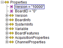
Fig. 19 BoardProperties Root Node
Version
This node holds detailed information about the API and the input-source used for generating the properties file. Its main use is for documentation purposes.
BoardInfo
This node holds detailed information about the board itself like
Serial number
Firmware version information
Administrative information about the calibration
SystemInfo
This node holds detailed information about the enclosure the board is residing in. For example the PXI-slot-number could be extracted from here to be shown in the application User Interface.
Variable
This node only serves internal purposes and is not meant to be used by the application directly.
BoardFeatures
This section roughly describes the acquisition capabilities of the board at hand. This example shows a TRION-2402-dACC-6-BNC (analog sampling board with six analog channels)
<BoardFeatures>
    <AI>
        <Channels>6</Channels>
        <Resolution Count = "2" Default = "0">
            <ID0>24</ID0>
            <ID1>16</ID1>
        </Resolution>
    </AI>
    <ARef>
        <Channels>1</Channels>
    </ARef>
    <CNT>
        <Channels>2</Channels>
        <Resolution>32</Resolution>
        <TimeBase Unit = "MHz">80</TimeBase>
    </CNT>
    <BoardCNT>
        <Channels>1</Channels>
        <Resolution>32</Resolution>
        <TimeBase Unit = "MHz">80</TimeBase>
    </BoardCNT>
    <ChnNoStart>
        <AI/>
        <CNT/>
        <BoardCNT/>
        <DI/>
        <CAN/>
    </ChnNoStart>
</BoardFeatures>
From this information the application can deduce:
The board has six analog input channels
The analog input channels can be used with 16 and 24 Bit resolution
The default resolution is 24 Bit
2 counter channels are available with a 80MHz resolution
1 internal counter channel is available - a so called BoardCounter
No digital or CAN channels are available
AcquisitionProperties
This node holds very detailed information about the various settings necessary for the synchronization capabilities of the board and general settings affecting the acquisition itself (e.g. the sample-rate).
This node is very elaborate and needs only to be considered in detail for more advanced setup. Discussing these nodes in detail is beyond the scope of this document. So its contents are not fully shown here.
One more general sub-node within this node is AcqProp
AcqProp
This node holds generic setup information about the acquisition parameters for this board.
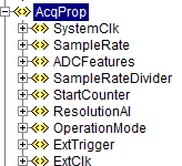
Fig. 20 BoardProperties - AcqProp Node
Illustration 7 - BoardProperties - AcqProp Node
The most interesting sub-elements within here probably are:
SampleRate
OperationMode
ResolutionAI
SampleRate
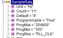
Fig. 21 BoardProperties - SampleRate Node
This allows the application to know the upper and lower limits of the available sample-rates. In this case the range goes from 100 Samples/second up to 200 kSamples/second, 204800 Hz to be exact.
OperationMode
<OperationMode Count = "2" Default = "0">
    <ID0>Slave</ID0>
    <ID1>Master</ID1>
</OperationMode>
This property allows selecting the predefined roles of the board within a multi-board system. Together with the information about external clocking and external triggering this will automatically set up the routing for the internal trigger- and clock-lines to a predefined state that is suited to make the board fulfill its desired role.
ResolutionAI
<ResolutionAI Count = "2" Default = "0">
    <ID0>24</ID0>
    <ID1>16</ID1>
</ResolutionAI>
This property allows setting the analog channels to a desired ADC-resolution.
ChannelProperties
This node gives exhaustive information about all available acquisition channels and all their settable properties.
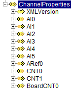
Fig. 22 BoardProperties - ChannelProperties Node
In this case, the XML-File shows that:
There are six analog channels, labeled AI0 to AI5
Two counter channels, labeled CNT0 and CNT 1
One internal counter (the Board-Counter), labeled BoardCNT0
The basic layout for all the channel-types is always the same and allows for easy initial navigation within the node.
The analog channel 0 is used as example to explain this in more depth.
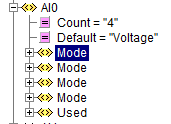
Fig. 23 BoardProperties - AI0 Channel Node
The first layer always holds:
a list of supported operation modes
the Used-flag itself as it is independent of the chosen mode
In this example the list of modes is:
<Mode Mode = “Calibration”>
<Mode Mode = “Voltage”>
<Mode Mode = “Resistance”>
<Mode Mode = “IEPE”>
Element AI0
Looking at AI0 Channel Node, the default indicates that the mode “Voltage” is set as default.
Each of the modes lists its own associated properties.
The list of applicable properties may vary between the modes. Properties which are only mentioned in some modes but not in others simply indicate that they would have no actual meaning in the modes where they are not listed.
Here within the analog channels this is not the case. An example would be counter-channels that have a mode called “Simple Event Counting” - that only takes one input signal - and therefore have only one source mentioned in this mode but also support a “gated event counting” - that will take two distinct input-signals - and therefore has two separate sources settable.
Taking the Voltage mode as an example:
Voltage/Range
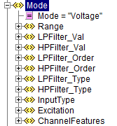
Fig. 24 BoardProperties - Voltage Mode
This is the exhaustive list of supported properties for an analog channel in voltage mode.
The most obvious property here is Range:
<Range
    Unit = "V"
    Count = "7"
    Default = "0"
    Programmable = "True"
    MinInputOffset = "-200"
    MaxInputOffset = "200"
    MinOutputOffset = "-150"
    MaxOutputOffset = "150"
    MinTotalOffset = "-300"
    MaxTotalOffset = "300"
    AmplRangeMin = "0.01"
    AmplRangeMinUnit = "V"
    AmplRangeMax = "100"
    AmplRangeMaxUnit = "V"
    ProgMax = "100"
    ProgMin = "-100">
    <ID0 MinInputOffset = "-100" MaxInputOffset = "100">100</ID0>
    <ID1>30</ID1>
    <ID2>10</ID2>
    <ID3>3</ID3>
    <ID4>1</ID4>
    <ID5>0.3</ID5>
    <ID6>0.1</ID6>
    <ID7>0.03</ID7>
</Range>
From this information the application can deduce:
The analog input supports ranges from 0.03V to 200V
The default input range is 200V
It is freely programmable. So any value between min and max can be set and the hardware is not limited to the values presented in the list
Various information about offsets. Explaining these in detail is beyond the scope of this overview document.
Using the BoardProperties XML-File
With the overview provided in mind one obvious use case for this document is to allow the application to perform some preliminary evaluation of settings before trying to apply them to the API.
One other use case would be that it easily allows the application to decide about setup-information shown in the user-interface if needed. It would be easy to just offer such options in the UI that are actually supported by the board for the given mode.
One less obvious information the document provides is information needed for the string based functions – namely the target string and the item-identifier.
Deriving Target Strings and Item IDs from the Document
As shown all logical properties are addressed by strings.
As a rule of thumb one can assume that the target string matches the path within the XML-File starting from the root but omitting the first node-level.
The last element identifies the Items. Anything that remains in before is part of the target-string.
This is entirely true for the acquisition properties and slightly different for the channel properties. The detailed rational for this approach is provided within this chapter along with a couple of examples.
Acquisition Properties
While the examples provided here will look awfully complicated on first sight, the procedure itself is generic enough to become natural to the application developer very quickly.
Example: How to setup/retrieve the SampleRate with the string based functions
Path within the XML-File: AcquisitionProperties/AcqProp/SampleRate
Derived target and item-string for the string based functions:
Applying the rule of omitting the first node-level: AcqProp/SampleRate
Last part is the item: “SampleRate”
Remainder for the target string: AcqProp
As the target-string always needs the BoardID as part of it the complete Target string is: “BoardID0/AcqProp”
So the final function call looks like:
DeWeSetParamStruct_str( "BoardID0/AcqProp", "SampleRate", "20000" );
Example: How to setup the ResolutionAI
Path within XML-File: AcquisitionProperties/AcqProp/ResolutionAI
Derived target- and item-string:
Target: “BoardID0/AcqProp”
Item: “ResolutionAI”
Final function call:
DeeSetParamStruct_str( "BoardID0/AcqProp", "ResolutionAI", "16" );
Channel Properties
As discussed in the first level on a single channel within the XML-File is a list of various modes grouping the properties meaningful for the given mode.
This has two consequences when deriving target and item information:
Mode itself is a valid Item
When addressing any property the mode-node is omitted within the target
Example: How to set the mode of an analog channel to Resistance
Path within XML-File: ChannelProperties/AI0/Mode Derived target- and item-string:
Target: “BoardID0/AI0”
Item: “Mode”
Final function call:
DeWeSetParamStruct_str( "BoardID0/AI0", "Mode", "Resistance" );
Example: How to set the Range of an analog channel in Resistance-mode
Path within XML-File: ChannelProperties/AI0/Mode/Range
Derived target- and item-string:
Target: “BoardID0/AI0”
Item: “Range”
Final function call:
DeWeSetParamStruct_str( "BoardID0/AI0", "Range", "3000" );
Complex property notations
Some properties have either complex relations to other properties or have a more complex mathematical ruleset needed to determine their constraints. Some properties are read-only information, and are not meant to be set by an application.
Those things are indicated with xml-attributes.
List of xml-attributes indicating a complex property
Atributename |
Value |
Meaning |
|---|---|---|
Config |
False |
Indicates a read-only-property with a static value, or no relevant value at all, only providing taxative information Example: Node “ChannelFeatures” |
Config |
Derived |
Indicates a read-only-property with a value that is derived from other properties. Example: Node “ShuntResistance” in bridge-mode on a TRION-18XX-MULTI |
Calculated |
Indicates a property where some or all constraints are dynamic and can be calculated with a given mathematical expression see Calculated values notations Example: Node “ShuntTarget” in bridge-mode on a TRION-18XX-MULTI |
|
Subkey |
various |
Indicates a property that depends in its validity on the setting of a different property. see ReferenceNode see Complex inter-property dependency notations Example: Node “BridgeRes” in bridge-mode on a TRION-18XX-MULTI |
ReferenceNode |
various |
Holds a semicolon seperated list of property-names that are affect in their constraint-set by changes of this property. see Subkey see Complex inter-property dependency notations Example: Node “InputType” in bridge-mode on a TRION-18XX-MULTI |
Complex inter-property dependency notations
More complex measurement modes may have complex dependencies between single properties. Selecting one specific property-value can shrink or widen the selection on other properties.
If a property influences the constraints of another property this is indicated with the xml-attribute “ReferenceNode” on property-node-level.
Warning
One property may influnece more than one other property. The value of the xml-attribute “ReferenceNode” holds a semicolon seperated list of affected attributes.
For example “ShuntType;Range”
Implicit Property selector mechanism
In Bridgemode exists an implicite dependency between “Excitation” and “Range”. This dependency is not annotated in the xml-structure. When using voltage-excitation the “Range”-node to use is the one with “Unit” = “mV/V”. When using current-excitation the “Range”-node to use is the one with “Unit” = “mV/mA”.
Explicit Property selector mechanism
A property may influence a differnt property in a way, that the most clear way of communicating this is by using a different definitionset for the influenced property.
The following exmple will help to make this more clear.
<InputType Count = "9" Default = "0" ReferenceNode = "BridgeRes">
    <ID0 Type = "External">BRFULL</ID0>
    <ID1 Type = "External">BRFULL5W</ID1>
    <ID2 Type = "External">BRHALF</ID2>
    <ID3 Type = "External">BRHALF4W</ID3>
    <ID4 Type = "Internal">BRQUARTER3W</ID4>
    <ID5 Type = "Internal">BRQUARTER4W</ID5>
    <ID6 Type = "Internal">CompletionVoltage</ID6>
    <ID7 Type = "Internal">LineVoltageDrop</ID7>
    <ID8 Type = "NA">Short</ID8>
</InputType>
<BridgeRes
    Unit = "Ohm"
    Count = "3"
    Default = "2"
    Subkey = "Type"
    Type = "Internal">
    <ID1>1000</ID1>
    <ID2>350</ID2>
    <ID7>120</ID7>
</BridgeRes>
<BridgeRes
    ProgMin = "50"
    ProgMax = "10000"
    Unit = "Ohm"
    Count = "2"
    Default = "0"
    Subkey = "Type"
    Type = "External">
    <ID0>350</ID0>
    <ID1>120</ID1>
</BridgeRes>
<BridgeRes
    Count = "0"
    Subkey = "Type"
    Type = "NA"/>
In this exmple the property “InputType” determines which definition set of “BridgeRes” is valid.
InputType has the xml-attribute “ReferenceNode” with a value of “BridgeRes”. This indicates, that “BridgeRes” depends on “InputType”.
Each ID node (ID0 to ID8) of “InputType” has a xml-attribute “Type”. The name of this attribute can differ from “Type”. The referenced node(s) establish a relation to this attribute.
On the same xml-level as “InputType” there are 3 nodes “BridgeRes”. Each of these nodes has a xml-attribute “Subkey”. The value of “Subkey” determines which xml-attribute-name determines the selection of this node. In this example “Subkey” has the value of “Type”. This indicates, that the “Type”-Attributes on ID-node-level in “InputType” needs to be looked at.
The “Subkey” xml-attribute is followed with a “Type” attribute. The actual name of this attribute is always the same, as the value of the “Subkey” attribute. The value of the “Type” xml-attribute now is the value of the “Type” xml-attributes from “InputType” to look for a match.
Examples:
If “InputType” is set to a value of “BRQUARTER3W”, “BRQUARTER4W”, “CompletionVoltage”or “LineVoltageDrop” the Type-attribute in “InputType” would have the assigned value of “Internal”. So the 1st BridgeRes Node has to be applied to determine the definition-set for BridgeRes. (As the 1st node has “SubKey”=”Type” and “Type=”Internal”).
<InputType Count = "9" Default = "0" ReferenceNode = "BridgeRes">
    <ID4 Type = "Internal">BRQUARTER3W</ID4>
    <ID5 Type = "Internal">BRQUARTER4W</ID5>
    <ID6 Type = "Internal">CompletionVoltage</ID6>
    <ID7 Type = "Internal">LineVoltageDrop</ID7>
</InputType>
<BridgeRes
    Unit = "Ohm"
    Count = "3"
    Default = "2"
    Subkey = "Type"
    Type = "Internal">
    <ID1>1000</ID1>
    <ID2>350</ID2>
    <ID7>120</ID7>
</BridgeRes>
If “InputType” is set to a value of “BRFULL”, “BRFULL5W”, “BRHALF” or “BRHAL4W” the Type-attribute in “InputType” would have the assigned value of “External” So the 2nd BridgeRes Node has to be applied to determine the definition- set for BridgeRes. (As the 2nd node has “SubKey”=”Type” and “Type=”External”).
<InputType Count = "9" Default = "0" ReferenceNode = "BridgeRes">
    <ID0 Type = "External">BRFULL</ID0>
    <ID1 Type = "External">BRFULL5W</ID1>
    <ID2 Type = "External">BRHALF</ID2>
    <ID3 Type = "External">BRHALF4W</ID3>
</InputType>
<BridgeRes
    ProgMin = "50"
    ProgMax = "10000"
    Unit = "Ohm"
    Count = "2"
    Default = "0"
    Subkey = "Type"
    Type = "External">
    <ID0>350</ID0>
    <ID1>120</ID1>
</BridgeRes>
If “InputType” is set to a value of “Short” the Type-attribute in “InputType” would have the assigned value of “NA” So the 3rd BridgeRes Node has to be applied to determine the definition-set for BridgeRes. (As the 3rd node has “SubKey”=”Type” and “Type=”NA”). In this case this results in an empty definition-set indicating that this property is not used in that combination.
<InputType Count = "9" Default = "0" ReferenceNode = "BridgeRes">
    <ID8 Type = "NA">Short</ID8>
</InputType>
<BridgeRes
    Count = "0"
    Subkey = "Type"
    Type = "NA"/>
Everytime the application sets a property with depending nodes, API evaluates this information an adjusts it’s internal validity checks according. If the previously set value of the depending property would still be valid after reevaluation the value will be left unchanged by TRION-API. If the previously set value of the depending property would be invalid the value will be set to the given Default of the newly selected definition- set.
Example 1: “InputType” = “BRFULL” “BridgeRes” = “1000 Ohm” (legal, as “BridgeRes” with “Type”=”External is freely programmable”)
change “InputType” to “BRQUARTER3W” This changes the “BridgeRes” to “Type”=”Internal”. “1000 Ohm” is in the list of valid options for this table (ID1), so the value remains unchanged.
Example 2: “InputType” = “BRFULL” “BridgeRes” = “420 Ohm” (legal, as “BridgeRes” with “Type”=”External is freely programmable”)
change “InputType” to “BRQUARTER3W” This changes the “BridgeRes” to “Type”=”Internal”. As this node is not programmable, and a value of “420 Ohm” is not within the list of valid values, API has to reset this to it’s default of “350 Ohm”.
Calculated values notations
Being a static document, the boardproperties document can not directly transport dynamic values.
To transport such dependencies the xml-node will hold an attribute named “Calculated”.
<ShuntTarget
    Unit = "mV/V"
    Count = "1"
    Default = "0"
    Programmable = "True"
    Calculated = ""
    ProgMin = "10.0 * 1e-6 * 'R_BRIDGE' / (2.0 * 'EXCVoltage') * 1e3"
    ProgMax = "75.0 * 1e-6 * 'R_BRIDGE' / (2.0 * 'EXCVoltage') * 1e3">
        <ID0>2</ID0>
        <Setting VariableName = "R_BRIDGE" Type = "AI0" Path = "" Item = "BridgeRes" Unit = "Ohm"/>
        <Setting VariableName = "EXCVoltage" Type = "AI0" Path = "" Item = "Excitation" Unit = "V"/>
</ShuntTarget>
This example is from a TRION3-1820-MULTI-4-D in bridge-mode. The maximum and minimal valid values are mathematically dependent on the brige-resistance and the voltage-excitation.
![ProgMin = \frac{10.0 * 10^6 * R\_BRIDGE[\Omega]}{2 * 10^3 * EXCVoltage[V]}](../_images/math/35ded87c36afce09a9d350976818875e6dfa1da1.png)
![ProgMax = \frac{75.0 * 10^6 * R\_BRIDGE[\Omega]}{2 * 10^3 * EXCVoltage[V]}](../_images/math/dbb4dda73fd849fef09234ece7c71ef97f262195.png)
The ‘Setting’-nodes indicate how to obtain the values needed in the calculation. Those values should be accessed by DeWeGetParamStruct_str-commands.
xmlattribute |
explaination |
|---|---|
VariableName |
Name of a variable used by the equation(s)
eg “R_BRIDGE”
|
Type Path |
These two attributes together form the targe part for the DeWeGetParamStruct_str call: “BoardId[X]\[Type]\[Path]” BoardId[X]: the board-id of the current board if “Path” is empty the final backslash shall be ommited |
Item |
The command part for the DeWeGetParamStruct_str call. |
Unit |
For informational purposes |
So in this example the two varaibles should be obtained with the following commands:
DeWeGetParamStruct_str("BoardID0\\AI0", "BridgeRes", R_BRIDGE_var, sizeof());
DeWeGetParamStruct_str("BoardID0\\AI0", "Excitation", EXCVoltage_var, sizeof());
With these two values at hand the values for ProgMin and ProgMax can be calculated.
BoardConfig XML-File
Purpose of the File
The detailed layout of the configuration-file is board specific. It can be derived from the content of the BoardProperties XML-File.
The file has three major sections:
<BoardInfo>
This section holds basic information about the board from which this configuration was generated from. This includes the BaseModel-Number and the human readable BoardName (BoardType, eg. TRION-BASE).
<Acquisition>
This is the counterpart to the Node <AcquisitionProperties> in the BoardProperties-XML-Document.
Each property from the BoardProperties-XML-Document, that is not marked with the attribute “Config = ‘False’” is also present in the <Acquisition> Node in the configuration document.
This includes some obvious information like for example the “SampleRate” as well, as for example detailed routing information for the PXI-trigger-lines or the Star-Hub.
<Channel>
This is the counterpart to the Node <ChannelProperties> in the BoardProperties-XML-document.
Each single channel is present within this node, with each of the settable properties, that is not marked with the attribute “Config = ‘False’” inside the BoardProperties-XML-document.
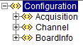
Fig. 25 Configuration-XML major sections
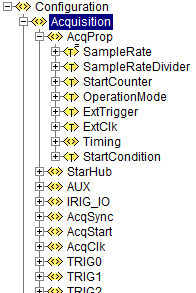
Fig. 26 Configuration XML Section: Acquisition
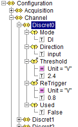
Fig. 27 Configuration XML Section: Channel
Result XML Document
The result xml-document has the same layout, as the configuration xml-document.
It’s main purpose is to provide a fine granulated feedback about any set-configuration command. When loading (setting) a configuration, each property is applies one after the other. Every single setting-command (this means every set single property) ends up in a defined result state. Ideally the operation succeeds with ERR_NONE. However - as any arbitrary configuration can be presented to any board, this isnot guaranteed at all.
To make diagnostics easier, this result-file offers the possibility to see the exact result of each single property.
Depending on the API-configuration itself, either all results are returned, or only results <> ERR_NONE.
The following figure shows an example for a result-file, when trying to apply a 8-AI-Channel-board configuration to a board, that only supports 6 AI-channels.
All settings are applied ok, except for the non-existing channels AI6 and AI7.
<?xml version="1.0"?>
<Results>
    <Acquisition>
        <AcqProp>
            <StartCondition>Warning -190910, WARNING_STARTCONDITION_NOT_USED (-190910)</StartCondition>
        </AcqProp>
    </Acquisition>
    <Channel>
        <AI6>
            <Mode>Error 120012, ERROR_AI_CHANNEL_NOT_VALID (120012)</Mode>
        </AI6>
        <AI7>
            <Mode>Error 120012, ERROR_AI_CHANNEL_NOT_VALID (120012)</Mode>
        </AI7>
    </Channel>
</Results>
Scan Descriptor
TODO
TEDS
TODO